Uml Class Diagram Table For Bank
This is the next installment in a series of articles about the essential diagrams used within the Unified Modeling Language, or UML. In my previous article on sequence diagrams, I shifted focus away from the UML 1.4 spec to OMG's Adopted 2.0 Draft Specification of UML (UML 2). In this article, I will discuss Structure Diagrams, which is a new diagram category that has been introduced in UML 2. Because the purpose of this series is to educate people about the notation elements and their meanings, this article focuses mainly on the class diagram. The reason for this will soon become clear. Subsequent articles will cover other diagrams included in the structure category.
I also want to remind readers that this series is about UML notation elements, and that these articles are not meant to provide guidance on the best approach for modeling, or how to determine what things should be modeled in the first place. Instead, the purpose of this article and of the series in general is to help with a basic understanding of notation elements — their syntax and their meanings. With this knowledge you should be able to read diagrams and create your own diagrams using the proper notation elements.
This article assumes you have a rudimentary understanding of object-oriented design. For those of you who need a little assistance with OO concepts, you might try the Sun brief tutorial Object-Oriented Programming Concepts. Reading the sections "What Is a Class?" and "What Is Inheritance?" should give you enough understanding to make this article useful. In addition, David Taylor's book, Object-Oriented Technologies: A Manager's Guide, offers an excellent, high-level explanation of object-oriented design without requiring an in-depth understanding of computer programming.
The yin and yang of UML 2
Deploy with confidence
Consistently deliver high-quality software faster using DevOps Continuous Delivery. Edit your code anywhere with Git repos and issue tracking, deliver continuously with an automated pipeline, get Insights to improve quality, and more.
In UML 2, there are two basic categories of diagrams: structure diagrams and behavior diagrams. Every UML diagram belongs to one these two diagram categories. The purpose of structure diagrams is to show the static structure of the system being modeled. They include the class, component, and or object diagrams. Behavioral diagrams, on the other hand, show the dynamic behavior between the objects in the system, including things like their methods, collaborations, and activities. Example behavior diagrams are activity, use case, and sequence diagrams.
Structure diagrams in general
As I have said, structure diagrams show the static structure of the system being modeled. focusing on the elements of a system, irrespective of time. Static structure is conveyed by showing the types and their instances in the system. Besides showing system types and their instances, structure diagrams also show at least some of the relationships among and between these elements and potentially even show their internal structure.
Structure diagrams are useful throughout the software lifecycle for a variety of team members. In general, these diagrams allow for design validation and design communication between individuals and teams. For example, business analysts can use class or object diagrams to model a business's current assets and resources, such as account ledgers, products, or geographic hierarchy. Architects can use the component and deployment diagrams to test/verify that their design is sound. Developers can use class diagrams to design and document the system's coded (or soon-to-be-coded) classes.
The class diagram in particular
UML 2 considers structure diagrams as a classification; there is no diagram itself called a "structure diagram." However, the class diagram offers a prime example of the structure diagram type, and provides us with an initial set of notation elements that all other structure diagrams use. And because the class diagram is so foundational, the remainder of this article will focus on the class diagram's notation set. By the end of this article you should have an understanding of how to draw a UML 2 class diagram and have a solid footing for understanding other structure diagrams when we cover them in later articles.
The basics
As mentioned, the purpose of the class diagram is to show the types being modeled within the system. In most UML models these types include:
- class
- interface
- data type
- component
UML uses a special name for these types: "classifiers." Generally, you can think of a classifier as a class, but technically a classifier is a more general term that refers to the other three types above as well.
Class name
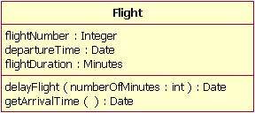
The UML representation of a class is a rectangle containing three compartments stacked vertically, as shown in Figure 1. The top compartment shows the class's name. The middle compartment lists the class's attributes. The bottom compartment lists the class's operations. When drawing a class element on a class diagram, you must use the top compartment, and the bottom two compartments are optional. (The bottom two would be unnecessary on a diagram depicting a higher level of detail in which the purpose is to show only the relationship between the classifiers.) Figure 1 shows an airline flight modeled as a UML class. As we can see, the name is Flight, and in the middle compartment we see that the Flight class has three attributes: flightNumber, departureTime, and flightDuration. In the bottom compartment we see that the Flight class has two operations: delayFlight and getArrivalTime.
Class attribute list
The attribute section of a class (the middle compartment) lists each of the class's attributes on a separate line. The attribute section is optional, but when used it contains each attribute of the class displayed in a list format. The line uses the following format:
Continuing with our Flight class example, we can describe the class's attributes with the attribute type information, as shown in Table 1.
Table 1. The Flight class's attribute names with their associated types
| Attribute Name | Attribute Type |
|---|---|
| flightNumber | Integer |
| departureTime | Date |
| flightDuration | Minutes |
In business class diagrams, the attribute types usually correspond to units that make sense to the likely readers of the diagram (i.e., minutes, dollars, etc.). However, a class diagram that will be used to generate code needs classes whose attribute types are limited to the types provided by the programming language, or types included in the model that will also be implemented in the system.
Sometimes it is useful to show on a class diagram that a particular attribute has a default value. (For example, in a banking account application a new bank account would start off with a zero balance.) The UML specification allows for the identification of default values in the attribute list section by using the following notation:
name : attribute type = default value For example:
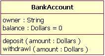
Showing a default value for attributes is optional; Figure 2 shows a Bank Account class with an attribute called balance, which has a default value of 0.
Class operations list
The class's operations are documented in the third (lowest) compartment of the class diagram's rectangle, which again is optional. Like the attributes, the operations of a class are displayed in a list format, with each operation on its own line. Operations are documented using the following notation:
name(parameter list) : type of value returned The Flight class's operations are mapped in Table 2 below.
Table 2. Flight class's operations mapped from Figure 3
| Operation Name | Parameters Return | Value Type | ||||
|---|---|---|---|---|---|---|
| delayFlight |
| N/A | ||||
| getArrivalTime | N/A | Date |
Figure 3 shows that the delayFlight operation has one input parameter — numberOfMinutes — of the type Minutes. However, the delayFlight operation does not have a return value. (Note: The delayFlight does not have a return value because I made a design decision not to have one. One could argue that the delay operation should return the new arrival time, and if this were the case, the operation signature would appear as delayFlight(numberOfMinutes : Minutes) : Date.) When an operation has parameters, they are put inside the operation's parentheses; each parameter uses the format "parameter name : parameter type".
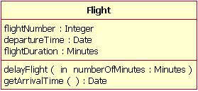
When documenting an operation's parameters, you may use an optional indicator to show whether or not the parameter is input to, or output from, the operation. This optional indicator appears as an "in" or "out" as shown in the operations compartment in Figure 3. Typically, these indicators are unnecessary unless an older programming language such as Fortran will be used, in which case this information can be helpful. However, in C++ and Java, all parameters are "in" parameters and since "in" is the parameter's default type according to the UML specification, most people will leave out the input/output indicators.
Inheritance
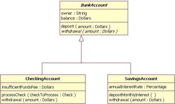
A very important concept in object-oriented design, inheritance, refers to the ability of one class (child class) to inherit the identical functionality of another class (super class), and then add new functionality of its own. (In a non-technical sense, imagine that I inherited my mother's general musical abilities, but in my family I'm the only one who plays electric guitar.) To model inheritance on a class diagram, a solid line is drawn from the child class (the class inheriting the behavior) with a closed, unfilled arrowhead (or triangle) pointing to the super class. Consider types of bank accounts: Figure 4 shows how both CheckingAccount and SavingsAccount classes inherit from the BankAccount class.
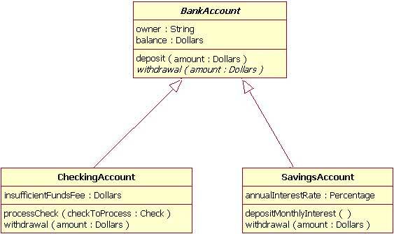
In Figure 4, the inheritance relationship is drawn with separate lines for each subclass, which is the method used in IBM Rational Rose and IBM Rational XDE. However, there is an alternative way to draw inheritance called tree notation. You can use tree notation when there are two or more child classes, as in Figure 4, except that the inheritance lines merge together like a tree branch. Figure 5 is a redrawing of the same inheritance shown in Figure 4, but this time using tree notation.
Abstract classes and operations
The observant reader will notice that the diagrams in Figures 4 and 5 use italicized text for the BankAccount class name and withdrawal operation. This indicates that the BankAccount class is an abstract class and the withdrawal method is an abstract operation. In other words, the BankAccount class provides the abstract operation signature of withdrawal and the two child classes of CheckingAccount and SavingsAccount each implement their own version of that operation.
However, super classes (parent classes) do not have to be abstract classes. It is normal for a standard class to be a super class.
Associations
When you model a system, certain objects will be related to each other, and these relationships themselves need to be modeled for clarity. There are five types of associations. I will discuss two of them — bi-directional and uni-directional associations — in this section, and I will discuss the remaining three association types in the Beyond the basics section. Please note that a detailed discussion of when to use each type of association is beyond the scope of this article. Instead, I will focus on the purpose of each association type and show how the association is drawn on a class diagram.
Bi-directional (standard) association
An association is a linkage between two classes. Associations are always assumed to be bi-directional; this means that both classes are aware of each other and their relationship, unless you qualify the association as some other type. Going back to our Flight example, Figure 6 shows a standard kind of association between the Flight class and the Plane class.

A bi-directional association is indicated by a solid line between the two classes. At either end of the line, you place a role name and a multiplicity value. Figure 6 shows that the Flight is associated with a specific Plane, and the Flight class knows about this association. The Plane takes on the role of "assignedPlane" in this association because the role name next to the Plane class says so. The multiplicity value next to the Plane class of 0..1 means that when an instance of a Flight exists, it can either have one instance of a Plane associated with it or no Planes associated with it (i.e., maybe a plane has not yet been assigned). Figure 6 also shows that a Plane knows about its association with the Flight class. In this association, the Flight takes on the role of "assignedFlights"; the diagram in Figure 6 tells us that the Plane instance can be associated either with no flights (e.g., it's a brand new plane) or with up to an infinite number of flights (e.g., the plane has been in commission for the last five years).
For those wondering what the potential multiplicity values are for the ends of associations, Table 3 lists some example multiplicity values along with their meanings.
Table 3. Multiplicity values and their indicators
| Indicator | Meaning |
|---|---|
| 0..1 | Zero or one |
| 1 | One only |
| 0.. | Zero or more |
| Zero or more | |
| 1..* | One or more |
| 3 | Three only |
| 0..5 | Zero to Five |
| 5..15 | Five to Fifteen |
Uni-directional association
In a uni-directional association, two classes are related, but only one class knows that the relationship exists. Figure 7 shows an example of an overdrawn accounts report with a uni-directional association.

A uni-directional association is drawn as a solid line with an open arrowhead (not the closed arrowhead, or triangle, used to indicate inheritance) pointing to the known class. Like standard associations, the uni-directional association includes a role name and a multiplicity value, but unlike the standard bi-directional association, the uni-directional association only contains the role name and multiplicity value for the known class. In our example in Figure 7, the OverdrawnAccountsReport knows about the BankAccount class, and the BankAccount class plays the role of "overdrawnAccounts." However, unlike a standard association, the BankAccount class has no idea that it is associated with the OverdrawnAccountsReport. (Note: It may seem strange that the BankAccount class does not know about the OverdrawnAccountsReport class. This modeling allows report classes to know about the business class they report, but the business classes do not know they are being reported on. This loosens the coupling of the objects and therefore makes the system more adaptive to changes.)
Packages
Inevitably, if you are modeling a large system or a large area of a business, there will be many different classifiers in your model. Managing all the classes can be a daunting task; therefore, UML provides an organizing element called a package. Packages enable modelers to organize the model's classifiers into namespaces, which is sort of like folders in a filing system. Dividing a system into multiple packages makes the system easier to understand, especially if each package represents a specific part of the system. (Note: Packages are great for organizing your model's classes, but it's important to remember that your class diagrams are supposed to easily communicate information about the system being modeled. In cases where your packages have lots of classes, it is better to use multiple topic-specific class diagrams instead of just producing one large class diagram.)
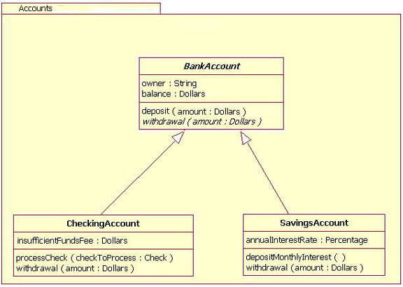
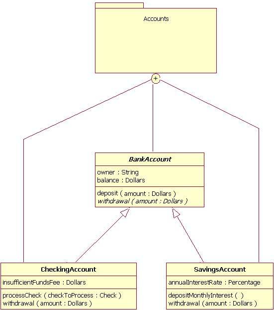
There are two ways of drawing packages on diagrams. There is no rule for determining which notation to use, except to use your personal judgement regarding which is easiest to read for the class diagram you are drawing. Both ways begin with a large rectangle with a smaller rectangle (tab) above its upper-left corner, as seen in Figure 8. But the modeler must decide how the package's membership is to be shown, as follows:
- If the modeler decides to show the package's members within the large rectangle, then all those members need to be placed within the rectangle. (Note: It's important to understand that when I say "all those members," I mean only the classes that the current diagram is going to show. A diagram showing a package with contents does not need to show all its contents; it can show a subset of the contained elements according to some criterion, which is not necessarily all the package's classifiers.) Also the package's name needs to be placed in the package's smaller rectangle (as shown in Figure 8).
- If the modeler decides to show the package's members outside the large rectangle then all the members that will be shown on the diagram need to be placed outside the rectangle. To show what classifiers belong to the package, a line is drawn from each classifier to a circle that has a plus sign inside the circle attached to the package (Figure 9).
Importance of understanding the basics
It is more important than ever in UML 2 to understand the basics of the class diagram. This is because the class diagram provides the basic building blocks for all other structure diagrams, such as the component or object diagrams (just to name a few).
Beyond the basics
At this point, I have covered the basics of the class diagram, but do not stop reading yet! In the following sections, I will address more important aspects of the class diagram that you can put to good use. These include interfaces, the three remaining types of associations, visibility, and other additions in the UML 2 specification.
Interfaces
Earlier, I suggested that you think of classifiers simply as classes. In fact, a classifier is a more general concept, which includes data types and interfaces.
A complete discussion of when and how to use data types and interfaces effectively in a system's structure diagrams is beyond the scope of this article. So why do I mention data types and interfaces here? There are times when you might want to model these classifier types on a structure diagram, and it is important to use the proper notation in doing so, or at least be aware of these classifier types. Drawing these classifiers incorrectly will likely confuse readers of your structure diagram, and the ensuing system will probably not meet requirements.
A class and an interface differ: A class can have an actual instance of its type, whereas an interface must have at least one class to implement it. In UML 2, an interface is considered to be a specialization of a class modeling element. Therefore, an interface is drawn just like a class, but the top compartment of the rectangle also has the text "«interface»", as shown in Figure 10. (Note: When drawing a class diagram it is completely within UML specification to put «class» in the top compartment of the rectangle, as you would with «interface»; however, the UML specification says that placing the "class" text in this compartment is optional, and it should be assumed if «class» is not displayed.)

In the diagram shown in Figure 10, both the Professor and Student classes implement the Person interface and do not inherit from it. We know this for two reasons: 1) The Person object is defined as an interface — it has the "«interface»" text in the object's name area, and we see that the Professor and Student objects are class objects because they are labeled according to the rules for drawing a class object (there is no additional classification text in their name area). 2) We know inheritance is not being shown here, because the line with the arrow is dotted and not solid. As shown in Figure 10, a dotted line with a closed, unfilled arrow means realization (or implementation); as we saw in Figure 4, a solid arrow line with a closed, unfilled arrow means inheritance.
More associations
Above, I discussed bi-directional and uni-directional associations. Now I will address the three remaining types of associations.
Association class
In modeling an association, there are times when you need to include another class because it includes valuable information about the relationship. For this you would use an association class that you tie to the primary association. An association class is represented like a normal class. The difference is that the association line between the primary classes intersects a dotted line connected to the association class. Figure 11 shows an association class for our airline industry example.

In the class diagram shown in Figure 11, the association between the Flight class and the FrequentFlyer class results in an association class called MileageCredit. This means that when an instance of a Flight class is associated with an instance of a FrequentFlyer class, there will also be an instance of a MileageCredit class.
Aggregation
Aggregation is a special type of association used to model a "whole to its parts" relationship. In basic aggregation relationships, the lifecycle of a part class is independent from the whole class's lifecycle.
For example, we can think of Car as a whole entity and Car Wheel as part of the overall Car. The wheel can be created weeks ahead of time, and it can sit in a warehouse before being placed on a car during assembly. In this example, the Wheel class's instance clearly lives independently of the Car class's instance. However, there are times when the part class's lifecycle is not independent from that of the whole class — this is called composition aggregation. Consider, for example, the relationship of a company to its departments. Both Company and Departments are modeled as classes, and a department cannot exist before a company exists. Here the Department class's instance is dependent upon the existence of the Company class's instance.
Let's explore basic aggregation and composition aggregation further.
Basic aggregation
An association with an aggregation relationship indicates that one class is a part of another class. In an aggregation relationship, the child class instance can outlive its parent class. To represent an aggregation relationship, you draw a solid line from the parent class to the part class, and draw an unfilled diamond shape on the parent class's association end. Figure 12 shows an example of an aggregation relationship between a Car and a Wheel.

Composition aggregation
The composition aggregation relationship is just another form of the aggregation relationship, but the child class's instance lifecycle is dependent on the parent class's instance lifecycle. In Figure 13, which shows a composition relationship between a Company class and a Department class, notice that the composition relationship is drawn like the aggregation relationship, but this time the diamond shape is filled.

In the relationship modeled in Figure 13, a Company class instance will always have at least one Department class instance. Because the relationship is a composition relationship, when the Company instance is removed/destroyed, the Department instance is automatically removed/destroyed as well. Another important feature of composition aggregation is that the part class can only be related to one instance of the parent class (e.g. the Company class in our example).
Reflexive associations
We have now discussed all the association types. As you may have noticed, all our examples have shown a relationship between two different classes. However, a class can also be associated with itself, using a reflexive association. This may not make sense at first, but remember that classes are abstractions. Figure 14 shows how an Employee class could be related to itself through the manager/manages role. When a class is associated to itself, this does not mean that a class's instance is related to itself, but that an instance of the class is related to another instance of the class.

The relationship drawn in Figure 14 means that an instance of Employee can be the manager of another Employee instance. However, because the relationship role of "manages" has a multiplicity of 0..*; an Employee might not have any other Employees to manage.
Visibility
In object-oriented design, there is a notation of visibility for attributes and operations. UML identifies four types of visibility: public, protected, private, and package.
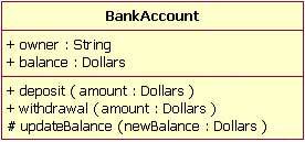
The UML specification does not require attributes and operations visibility to be displayed on the class diagram, but it does require that it be defined for each attribute or operation. To display visibility on the class diagram, you place the visibility mark in front of the attribute's or operation's name. Though UML specifies four visibility types, an actual programming language may add additional visibilities, or it may not support the UML-defined visibilities. Table 4 displays the different marks for the UML-supported visibility types.
Table 4. Marks for UML-supported visibility types
| Mark | Visibility type |
|---|---|
| Public | |
| # | Protected |
| – | Private |
| ~ | Package |
Now, let's look at a class that shows the visibility types indicated for its attributes and operations. In Figure 15, all the attributes and operations are public, with the exception of the updateBalance operation. The updateBalance operation is protected.
UML 2 additions
Now that we have covered the basics and the advanced topics, we will cover some of the new notations added to the class diagram from UML 1.x.
Instances
When modeling a system's structure it is sometimes useful to show example instances of the classes. To model this, UML 2 provides the instance specification element, which shows interesting information using example (or real) instances in the system.
The notation of an instance is the same as a class, but instead of the top compartment merely having the class's name, the name is an underlined concatenation of:
Instance Name : Class Name For example:
Because the purpose of showing instances is to show interesting or relevant information, it is not necessary to include in your model the entire instance's attributes and operations. Instead, it is completely appropriate to show only the attributes and their values that are interesting as depicted in Figure 16.

However, merely showing some instances without their relationship is not very useful; therefore, UML 2 allows for the modeling of the relationships/associations at the instance level as well. The rules for drawing associations are the same as for normal class relationships, although there is one additional requirement when modeling the associations. The additional restriction is that association relationships must match the class diagram's relationships and, therefore, the association's role names must also match the class diagram. An example of this is shown in Figure 17. In this example the instances are example instances of the class diagram found in Figure 6.
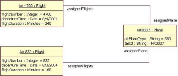
Figure 17 has two instances of the Flight class because the class diagram indicated that the relationship between the Plane class and the Flight class is zero-to-many. Therefore, our example shows the two Flight instances that the NX0337 Plane instance is related to.
Roles
Modeling the instances of classes is sometimes more detailed than one might wish. Sometimes, you may simply want to model a class's relationship at a more generic level. In such cases, you should use the role notation. The role notation is very similar to the instances notation. To model a class's role, you draw a box and place the class's role name and class name inside as with the instances notation, but in this case you do not underline the words. Figure 18 shows an example of the roles played by the Employee class described by the diagram at Figure 14. In Figure 18, we can tell, even though the Employee class is related to itself, that the relationship is really between an Employee playing the role of manager and an Employee playing the role of team member.

Note that you cannot model a class's role on a plain class diagram, even though Figure 18 makes it appear that you can. In order to use the role notation you will need to use the Internal Structure notation, discussed next.
Internal structures
One of the more useful features of UML 2 structure diagrams is the new internal structure notation. It allows you to show how a class or another classifier is internally composed. This was not possible in UML 1.x, because the notation set limited you to showing only the aggregation relationships that a class had. Now, in UML 2, the internal structure notation lets you more clearly show how that class's parts relate to each other.
Let's look at an example. In Figure 18 we have a class diagram showing how a Plane class is composed of four engines and two control software objects. What is missing from this diagram is any information about how airplane parts are assembled. From the diagram in Figure 18, you cannot tell if the control software objects control two engines each, or if one control software object controls three engines and the other controls one engine.

Drawing a class's internal structure will improve this situation. You start by drawing a box with two compartments. The top compartment contains the class name, and the lower compartment contains the class's internal structure, showing the parent class's part classes in their respective roles, as well as how each particular class relates to others in that role. Figure 19 shows the internal structure of Plane class; notice how the internal structure clears up the confusion.
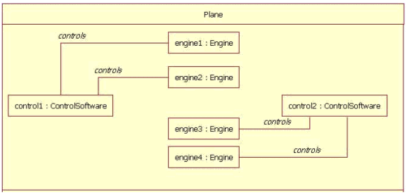
In Figure 20 the Plane has two ControlSoftware objects and each one controls two engines. The ControlSoftware on the left side of the diagram (control1) controls engines 1 and 2. The ControlSoftware on the right side of the diagram (control2) controls engines 3 and 4.
Summary and next steps
There are at least two important reasons for understanding the class diagram. The first is that it shows the static structure of classifiers in a system; the second reason is that the diagram provides the basic notation for other structure diagrams prescribed by UML. You will think the class diagram was created specially for you; but other team members will find them useful, too. Business analysts can use class diagrams to model systems from the business perspective. As we will see in other articles in this series on UML basics, other diagrams — including the activity, sequence, and statechart diagrams — refer to the classes modeled and documented on the class diagram.
To learn more about UML diagrams, check out an IBM Developer article about the component diagram.
Source: https://developer.ibm.com/articles/the-class-diagram/
Posted by: hondrosodetteees.blogspot.com
Posting Komentar untuk "Uml Class Diagram Table For Bank"